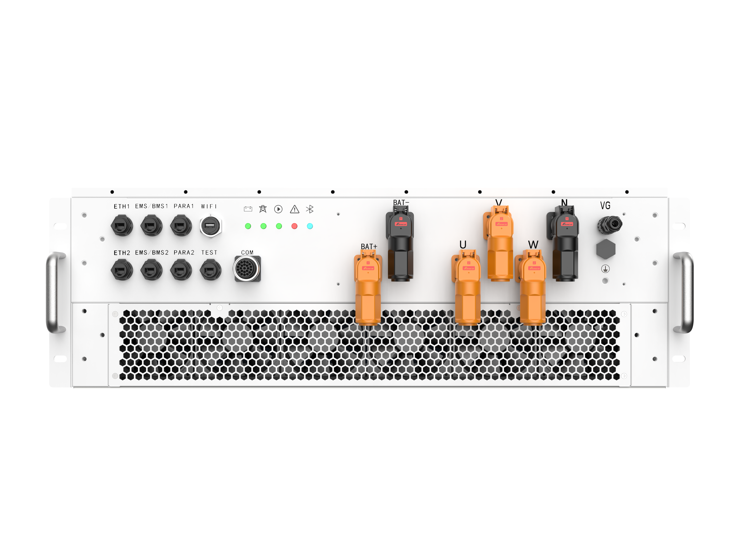
Large battery energy storage systems rarely depend on a single power conversion system (PCS). As project capacity grows, multiple PCS units can be connected in parallel to increase total charging and discharging capability while providing a modular path for system expansion. For EPC contractors, system integrators, and plant engineers, successful parallel operation depends on coordinated control, stable communication, accurate current sharing, and appropriate protection. Understanding these principles is essential when designing applications that use a PCS in battery energy storage system.
Why Multiple PCS Units Are Used in Large BESS Projects
A utility-scale BESS may require hundreds of kilowatts or several megawatts of bidirectional conversion capacity. Using multiple PCS units instead of one extremely large converter can create a modular architecture that simplifies equipment configuration, maintenance, transportation, and capacity expansion.
Each PCS converts DC power from the battery into AC power for the grid during discharge and converts AC power back into DC during charging. When several units operate in parallel, they must behave as one coordinated power-conversion system from the perspective of the wider electrical network.
This requires more than simply connecting AC terminals together. The control system must determine how much active and reactive power each unit should provide while maintaining stable electrical conditions across the common bus.
How PCS Units Synchronize With Each Other
Synchronization begins with a common understanding of electrical conditions. Grid-following PCS units typically monitor voltage, frequency, and phase at the AC connection point before generating current that is appropriately synchronized with the grid.
A supervisory controller or plant-level energy management system can then distribute active and reactive power commands among individual PCS units. Each converter uses its local control loops to follow the assigned reference while monitoring its own voltage, current, temperature, and protection status.
In a properly engineered system, the PCS units do not independently make conflicting decisions. Their operating references are coordinated so that the parallel system responds predictably to changing battery and grid requirements.
Current Sharing Is Central to Parallel Operation
One of the most important challenges in a multi-unit configuration is current and power sharing. If one PCS carries substantially more load than another, thermal stress and component utilization can become uneven.
Control strategies can divide the requested power among available units according to their rated capacity or operating status. For example, a plant controller may issue a total discharge command and allocate proportional power references to several PCS units.
Accurate sensing and fast control response are important because small differences in voltage measurement, impedance, or control parameters can influence how current is distributed. The interconnection design should therefore account for cable impedance, busbar arrangement, transformer configuration, and PCS ratings rather than assuming that parallel units will automatically share power evenly.
Communication and Control Architecture
Communication provides the coordination layer for a large parallel PCS installation. Depending on project architecture, individual PCS units may communicate with a master controller, battery management system, energy management system, or power plant controller.
The control hierarchy must clearly define responsibilities. The BMS monitors battery conditions and establishes operating limits, while the PCS manages electrical power conversion. A higher-level controller can coordinate total system power according to grid commands, state of charge, operating schedules, and other project requirements.
Communication failure handling is equally important. Engineers should define what happens if a PCS loses communication, receives an invalid command, or detects abnormal operating conditions. A robust design should allow affected units to enter an appropriate protective state without unnecessarily disrupting healthy units.
Grid Support and Dynamic Response
Parallel PCS operation becomes particularly important when a BESS is expected to provide grid services. Multiple converters may need to change their combined output quickly in response to frequency regulation, dispatch commands, renewable-energy fluctuations, or other grid requirements.
A battery energy storage system inverter PCS must therefore coordinate its internal control loops with plant-level commands. The total response depends not only on the individual converter’s capabilities but also on communication latency, controller architecture, measurement accuracy, and operating limits.
For large projects, engineers should verify the response behavior of the complete system rather than evaluating individual PCS specifications in isolation.
Enjoypowers’ 1500 Vdc PCS Approach
Enjoypowers offers a 1500 Vdc air-cooled PCS series intended for utility-scale applications. Its published product information identifies 125 kW, 150 kW, 215 kW, and 250 kW configurations for 400 Vac, 480 Vac, 690 Vac, and 800 Vac systems, respectively, and highlights validated sodium-ion battery support.
The company also states that the firmware includes sodium-ion charging profiles incorporating voltage windows, ramp rates, and state-of-charge estimation parameters adapted to the chemistry. According to the provided product information, BMS integration has been tested with multiple sodium-ion cell vendors.
For system integrators, chemistry-specific control support is relevant because the PCS does not operate independently from the battery. Charging limits, voltage behavior, SOC estimation, and BMS communication all influence how the complete storage system performs.
Designing Protection for Parallel PCS Systems
Protection coordination becomes more complex as the number of parallel converters increases. Each unit should have appropriate protection against conditions such as overcurrent, overvoltage, overheating, and abnormal grid conditions.
The common AC bus and DC battery architecture also require careful consideration. Engineers should evaluate fault-current paths, isolation requirements, grounding arrangements, disconnect devices, and protection coordination between PCS units, transformers, switchgear, and battery containers.
A modular design can help isolate a failed PCS from the rest of the system. If one unit trips while the remaining converters continue operating within their limits, overall BESS availability may be maintained without requiring the entire installation to shut down.
Scaling the System Without Losing Stability
Scalability is one of the main reasons developers adopt parallel PCS architectures. Additional units can increase conversion capacity without redesigning the entire power-conversion platform.
However, adding units changes the electrical and control environment. Engineers should verify communication addressing, control parameters, protection settings, transformer loading, harmonic behavior, and thermal conditions whenever the system is expanded.
The goal is to ensure that ten PCS units, for example, do not behave as ten unrelated converters. They should operate as coordinated elements within one engineered power-conversion system.
Building a Coordinated Multi-PCS Architecture
Successful parallel operation depends on coordination at several levels: electrical synchronization, power sharing, communication, protection, battery management, and plant-level control. Each individual PCS must remain within its operating limits while contributing predictably to the total system response.
For large BESS projects, the PCS in battery energy storage system architecture should therefore be considered as an integrated system rather than a collection of independent converters. Enjoypowers‘ 1500 Vdc utility-scale series, including its 125 kW air-cooled module and sodium-ion-oriented firmware and BMS integration capabilities, illustrates how PCS design is increasingly being adapted to different battery technologies and system architectures.
As storage projects continue to scale, modular parallel PCS operation provides a practical foundation for expanding conversion capacity. Careful synchronization, balanced loading, defined communication behavior, and coordinated protection are what turn multiple PCS units into a stable and manageable large-scale energy storage system.
